De vijf-positie schakelaar (“5-position switch”) is voor mij één van de moeilijkst aan te sluiten objecten gebleken. Tenminste, het aansluiten is niet zo moeilijk, maar de informatie die ik nodig had om uit te zoeken hoe ik met drie draadjes vijf standen op de Arduino moest aansluiten, bleek voor mij moeilijk te vinden. Een typisch geval dus van een post die andere mensen hopelijk een hoop tijd kan besparen!
Ik snap nog steeds niet honderd procent hoe het werkt maar je vindt hier in ieder geval de informatie om deze switch werkend aan te sluiten op een Arduino, inclusief een sketch die via de serial output laat zien welke stand je geselecteerd hebt. Het heeft me een complete middag gekost. Het antwoord vond ik uiteindelijk op het SparkFun forum, hoewel ik een melding kreeg dat deze site niet per definitie als veilig te beschouwen is, dus ik heb de informatie hierheen gekopiëerd – met bronvermelding.
Het principe van de vijf-positie schakelaar is dat je maar drie data-pinnen nodig hebt om vijf standen uit te lezen. Dat heeft er mee te maken dat er eigenlijk maar drie contact-punten zijn, maar dat deze ook per paar actief kunnen zijn. Je hebt dus als het ware stand 1, stand tussen 1 en 2 in, stand 2, et cetera.
Er zitten acht pootjes op de schakelaar (ik heb zelf deze versie), waarvan je alleen de linker vier gebruikt. Op de vierde van links (degene het meest bij de rand vandaan) sluit je de 5v output van je Arduino aan.
Voor de andere contacten doe je drie keer hetzelfde.
Dit is je breadboard:
3  6  9

2  5  8

1  4  7
Verticaal maken de cijfers contact (1, 2, 3).
Punt 1 sluit je met een 10K weerstandje aan op Ground
Punt 2 sluit je aan op het meest linker contact punt van je vijf-positie schakelaar
Punt 3 sluit je aan op Digital Pin 4 van je Arduino.
Punt 4 sluit je met een 10K weerstandje aan op Ground
Punt 5 sluit je aan op het op een na meest linker contact punt van je vijf-positie schakelaar
Punt 6 sluit je aan op Digital Pin 3 van je Arduino.
Punt 7 sluit je met een 10K weerstandje aan op Ground
Punt 8 sluit je aan op het op twee na meest linker contact punt van je vijf-positie schakelaar
Punt 9 sluit je aan op Digital Pin 2 van je Arduino.
Ik heb geprobeerd (zoals je zal zien in de sketch) om de interne pull-up op de Arduino zelf te gebruiken, maar bij mij ontstond er toen een lek waardoor de Arduino uitschakelde, dus ik heb uiteindelijk gewoon drie aparte weerstandjes gebruikt.
Hier leg ik alles nogmaals uit in een filmpje.
Hieronder de originele forum-post inclusief verhelderend plaatje.
Post op een forum die alles duidelijk beschrijft:
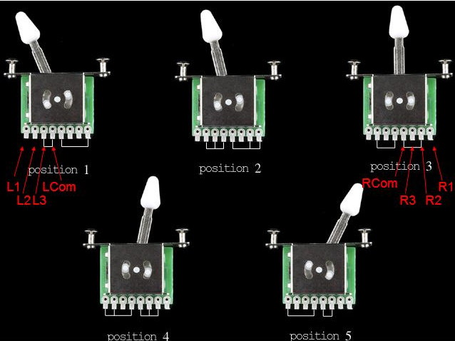
There are 2 separate switches in this one switch. Let me call them L and R for left and right. Looking at the picture the pin names would be (going from left to right in the pic) L1, L2, L3, LCom, RCom, R3, R2 and lastly R1. The L and R #1 pins are the outermost and have a dot above them. The L and R common pins are the innermost. The white lines show which pins are connected to which for each lever position.
I think the sketch only used one side, L or R (you pick) of the switch and has that side wired with Com connected to the Arduino 5V and each of the switch pins 1, 2 and 3 to a 10K pulldown resistor connected to Arduino ground. Pins 1, 2 and 3 of the switch are then also connected to the Arduino digital inputs pins 4, 3 and 2 respectively.
I’ve not looked too much at the sketch (included below) so I can’t comment on it but you should be able to figure it out from the pic below and the wiring above. See if it makes sense to you now.
EDIT : Looking at the code below I believe they used the left side pins so:
pinState1 = L3
pinState2 = L2
pinState3 = L1
Sketch:
(bron: https://ec2-67-202-61-130.compute-1.amazonaws.com/viewtopic.php?f=14&t=31542)
//First we declare our pins

#define pin1 2

#define pin2 3

#define pin3 4
//These variables will hold our digital read values
int pinState1 = 0;
int pinState2 = 0;
int pinState3 = 0;
//This will keep the last number sent to the terminal
//in this way we'll keep from cramming the terminal
//with a continuous stream of numbers.
int lastvalue = 0;
//And finally, this variable will hold the current switch position
int switchpos = 0;
void setup() {
// And... Serial
Serial.begin(9600);
// Now we set up our pinModes
// Set input pins
pinMode(pin1, INPUT);
pinMode(pin2, INPUT);
pinMode(pin3, INPUT);
// Set internal pull-ups (20K)
digitalWrite(pin1, HIGH);
digitalWrite(pin2, HIGH);
digitalWrite(pin3, HIGH);
}
void loop() {
//First we read the pins:
pinState1 = digitalRead(pin1);
pinState2 = digitalRead(pin2);
pinState3 = digitalRead(pin3);
// Now we'll use a list of if then conditions to determine the switch position
// because that's a nice transparent way of doing it. You could also
// use switch case or other methods. Basically, with each sweep we check to
// see if each pin is high, if a pin is high, we check the surrounding pins.
// with a little logic, we can deduce from that information which position the
// switch is in.
if(pinState1 == HIGH){
if(pinState2 == HIGH){switchpos = 2;}
else {switchpos = 1;}}
else if(pinState2 == HIGH){
if(pinState1 == HIGH){switchpos = 2;}
else if(pinState3 == HIGH){switchpos = 4;}
else {switchpos = 3;}}
else if(pinState3 ==HIGH){
if(pinState2 == HIGH){switchpos = 4;}
else {switchpos = 5;}}
//Now that we know which position our switch is in, let's print it to the terminal.
//But first, we'll make sure the switch has moved
if(switchpos != lastvalue){
Serial.print("Switch Position:");
Serial.println(switchpos);
Serial.println(""); //make some room
}
//Now remember that for the next sweep.
lastvalue = switchpos;
}